JeopardyPi
An almost perfect replica of America's Favorite Quiz Show® which runs on a Raspberry Pi
In this project, I built a fully functional Jeopardy game with a RaspberryPi, some buttons, a couple of screens, and plenty of very ugly Python code.
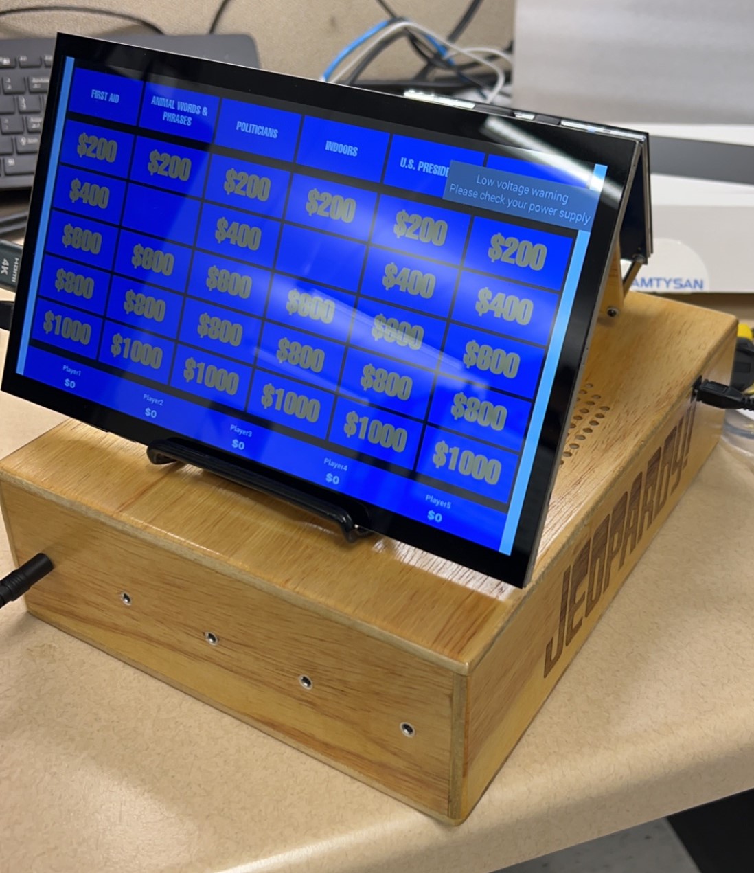
Overview
This project took several months, and I learned a lot about Python, the PyQt5 module, PCB design, and woodworking. The program handles almost everything in a normal Jeopardy game. It picks the categories and questions from a large database, ensures the correct number of Daily Doubles, and tells “Alex Trebek” who should select the next clue. Once the clue is selected, Alex uses his buzzer to show the clue to the players (he can read it beforehand) as well as allow the players to ring in. If a player rings in too early, he’s penalized with a quarter second delay just like the real game. Once a player rings in, Alex determines whether that person’s answer is correct, and the program keeps track of everyone’s score for them. When a Daily Double is selected, players hear the classic sound effect, and the lucky player is prompted to enter their wager. The only part where this Raspberry Pi remake doesn’t resemble the real show is Final Jeopardy. The Python still shows the clue, shows Alex the correct response, and plays the music, but players need to write their answers down on paper (I can’t afford THAT many screens).
Overall, I’m really happy with how this project turned out, and I definitely learned a lot. There are still a few things I would have changed, so be sure to read the end of this post if you’re thinking about building something like this yourself.
The Data
Obviously, I didn’t want to write down all of these questions myself. That would take forever, and then I would know all of the answers. I found this database on Kaggle and decided to use the teen questions because I thought that would make the game more fun for my family and me (we know our limits).
If you pull that data into an excel file, you’ll see that there’s not always a full category of clues. This is because sometimes the players don’t go quickly enough to answer all five clues in a category, so the people who log this stuff have no way of knowing what the remaining clues were. Obviously, this isn’t going to fly for JeopardyPi (rhyme intended). At the time, Chat GPT was just becoming a big thing. I had heard that it could write some basic code, so I decided to let it tackle the problem of cleaning up my excel file. I didn’t realize what all it was capable of, so I was sure it would fail, but after a bit of back and forth with me describing what I wanted it to do, it spit out some code, I ran it, and sure enough, my excel file was stripped of all the incomplete categories. I would later split the excel file into three different files. One file for the Jeopardy Round, one for the Double Jeopardy round, and one for Final Jeopardy. These can all be found on the GitHub.
Software
It’s all a big mess of Python, and I used PyQt5 to design the GUIs. PyQt5 offers a tool called Qt Designer which allows you to quickly design your GUIs with ease. Once satisfied, Qt Designer will fill in the Python file for you in order to put all of your buttons and labels in the right place.
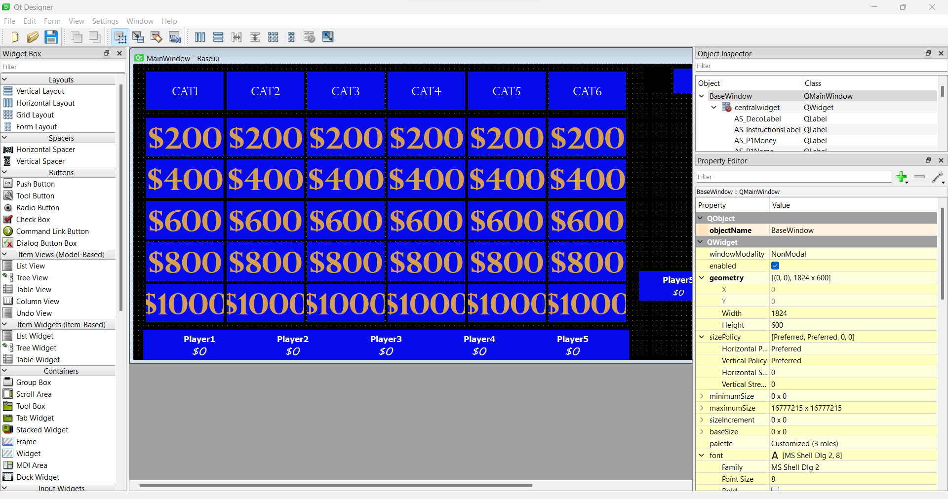
The main problems I ran into with Qt Designer were that I couldn’t figure out how to add custom fonts (I had to use Find and Replace in my code) and that things didn’t always look the same once they got to the Raspberry Pi. For instance, if you want to make a button the standard blue color that Jeopardy uses, you have to also give it a zero-pixel border, otherwise the Raspberry Pi displays a very light blue color. I don’t understand why this is the case, but if you’re curious, the specific stylesheet code is:
QPushButton{background-color:#060CE9; border:0px; color:#d69f4c;} This will set the button to be that Jeopardy blue color, and set the text within the button to be the yellowish color of the dollar amounts. Setting the border to zero pixels removes the animation that occurs when you press down on the screen, but I’m not sure why that’s necessary to get the color to display correctly.
Aside from the design of the GUIs, most of the rest of the Python is written in the Base.py file to implement the game. Everything in PyQt5 is event based which was new to me, so it led to a lot of variables which were used to keep track of what was going on and what should happen when players press their buzzers. This is the part of the project where the code got really ugly, so any feedback related to prettifying it is welcome. Ultimately, it works.
Also, if you want to go with the dual touchscreens as I have for this project, you may run into some problems with your touches not registering in the correct spot. Check out this forum post for the solution.
Hardware
PCB Design
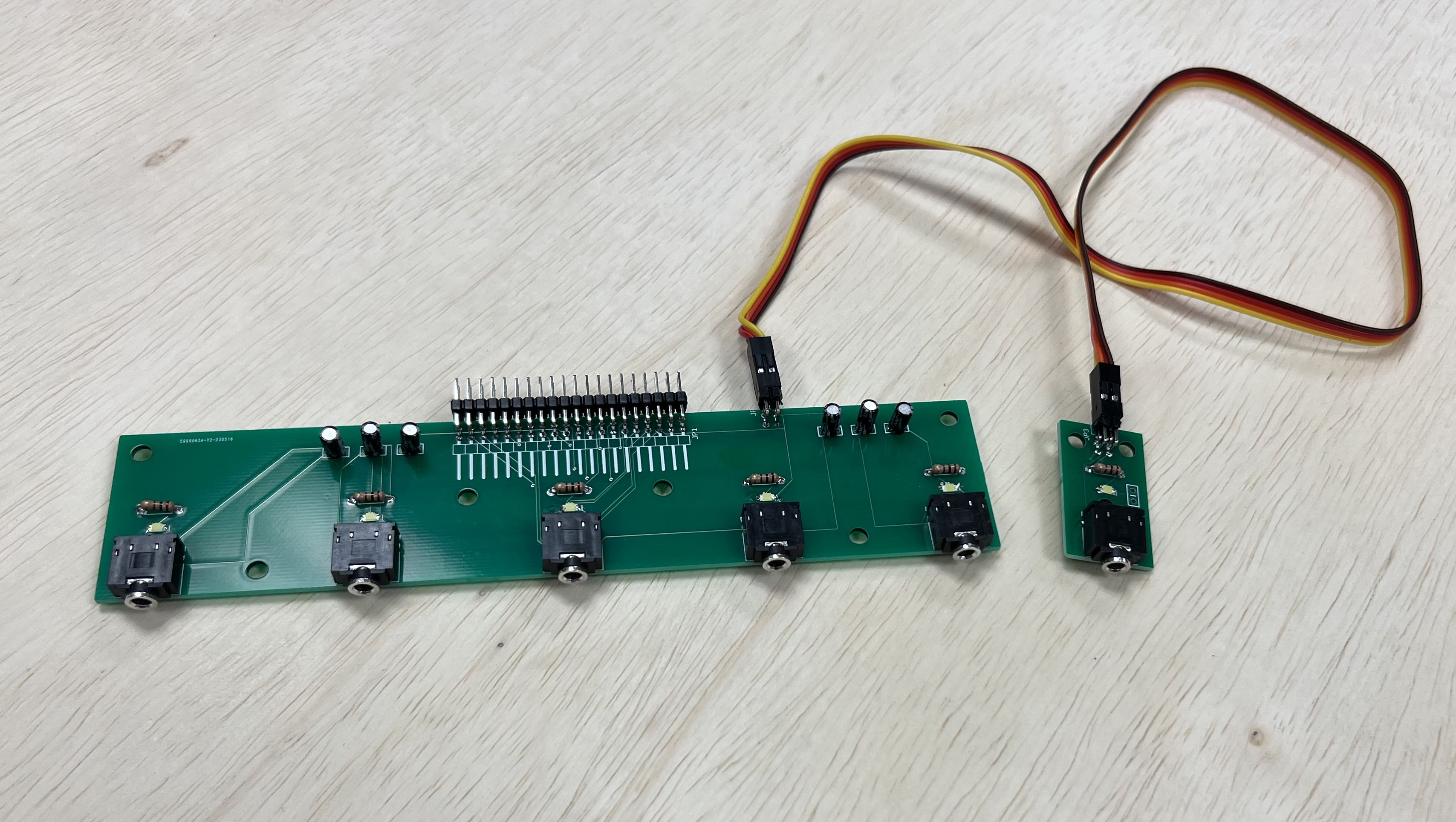
For this project I designed my very first PCB. I used Fusion 360 for the design (probably not the greatest choice but it’s a simple design) and ordered it through JLCPCB. There are actually two PCBs, a larger one for the players’ side which holds five audio jacks (this game allows for up to five players) and a smaller one for Alex’s buzzer on the opposite side of the housing.
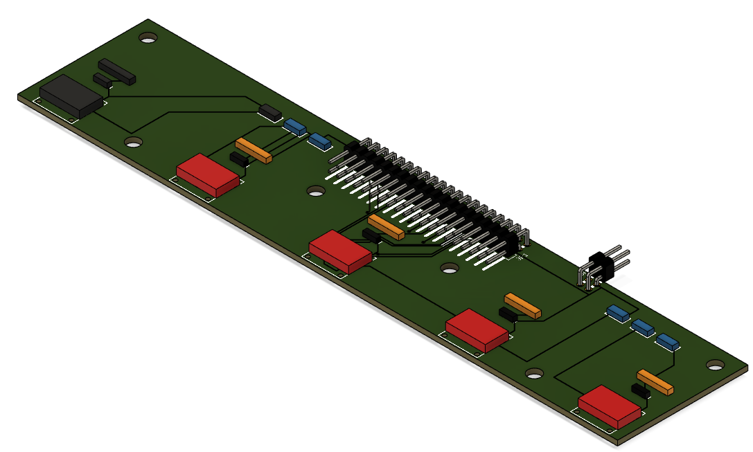
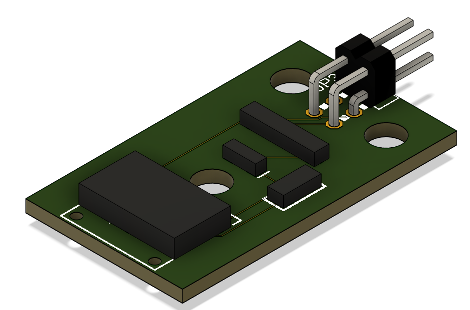
Each buzzer has a corresponding LED and resistor on the PCB which ultimately weren’t used. The PCB also features a capacitor for each buzzer to filter out noise in order to prevent false button presses. In hindsight, I’m fairly certain that these capacitors need to be as close to the button as possible meaning that those on the PCBs aren’t really doing much. I added capacitors inside the buzzers themselves to compensate for this. And since the buzzers plug in via an audio jack, it’s very easy to remove them for storage or in the event that less than five people are playing. The two PCBs connect to each other via a ribbon cable, and then the larger PCB connects to the Raspberry Pi via a ribbon cable. You may notice in the render of the larger PCB that the larger connector is facing backwards, but this is only a problem with the render. It was necessary to position the connector in such a way in order to ensure I didn’t confuse any of the connections. In reality, the boards look like this when soldered:
Wooden Box
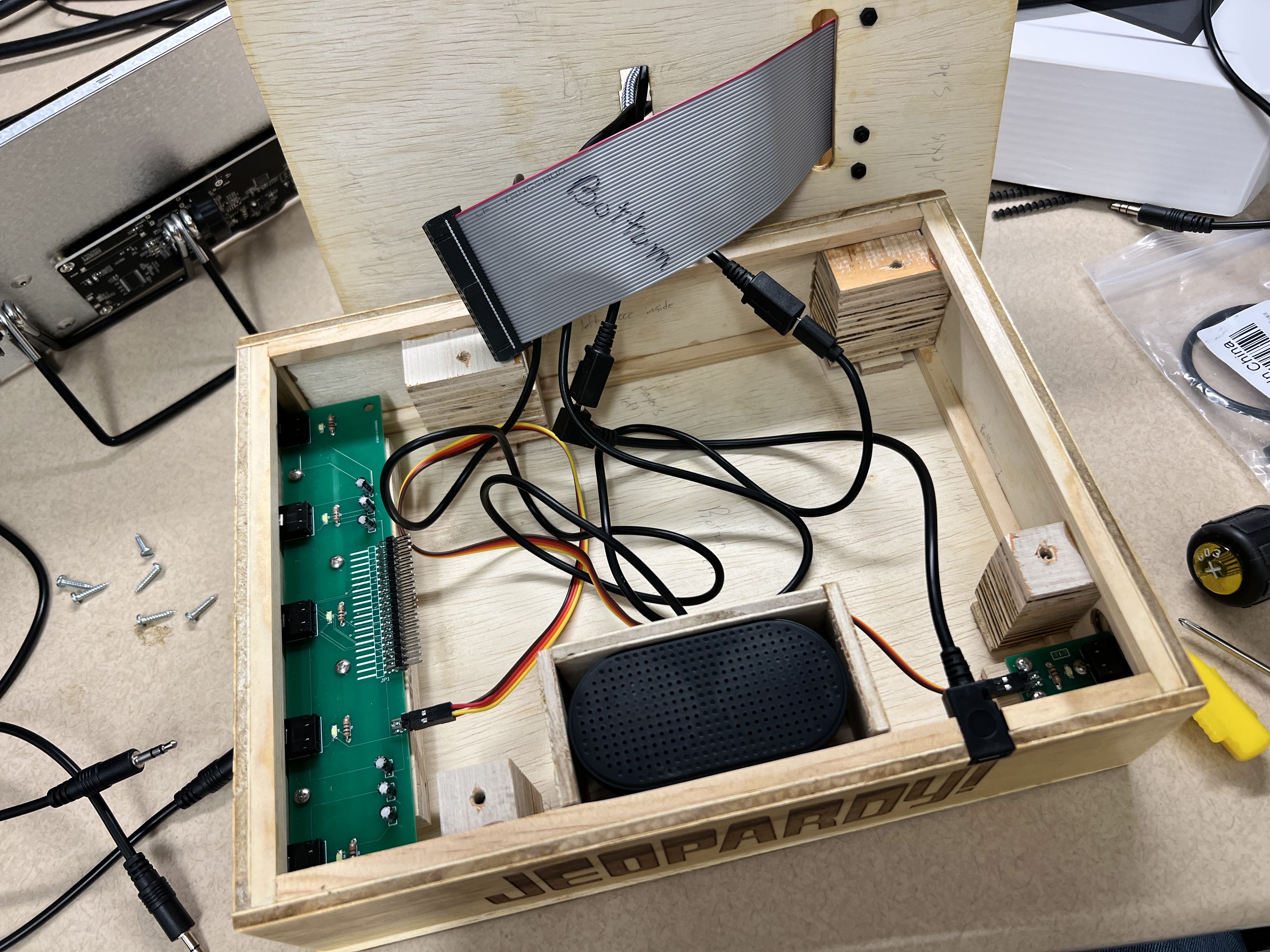
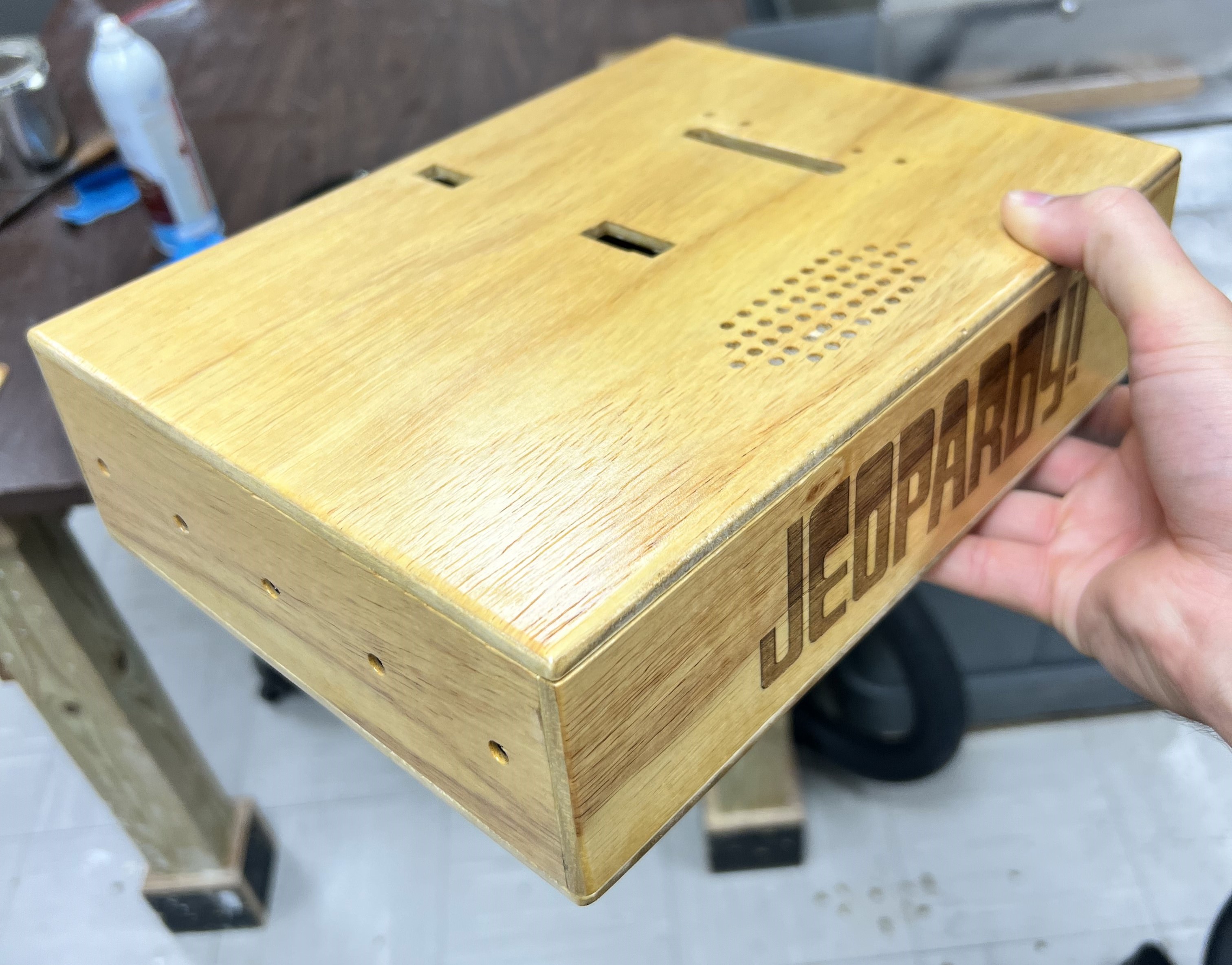
About half of this project was spent writing code, and the other half was spent simply building this box. I’m not very good at woodworking, but I had a lot of help from a coworker (shoutout to John) and some excellent laser engraving from a buddy of mine (shoutout to WorkinWithWillis). In the end, I think I did a couple clever things building this box, and I’m very happy with how it turned out. However, if you’re aiming to undertake this project and don’t want to spend way too many hours building a nice box, I highly recommend you learn how to design for a laser cutter and just pay someone to laser cut the wood for you. It’s pretty much guaranteed to be easier.
Buzzers
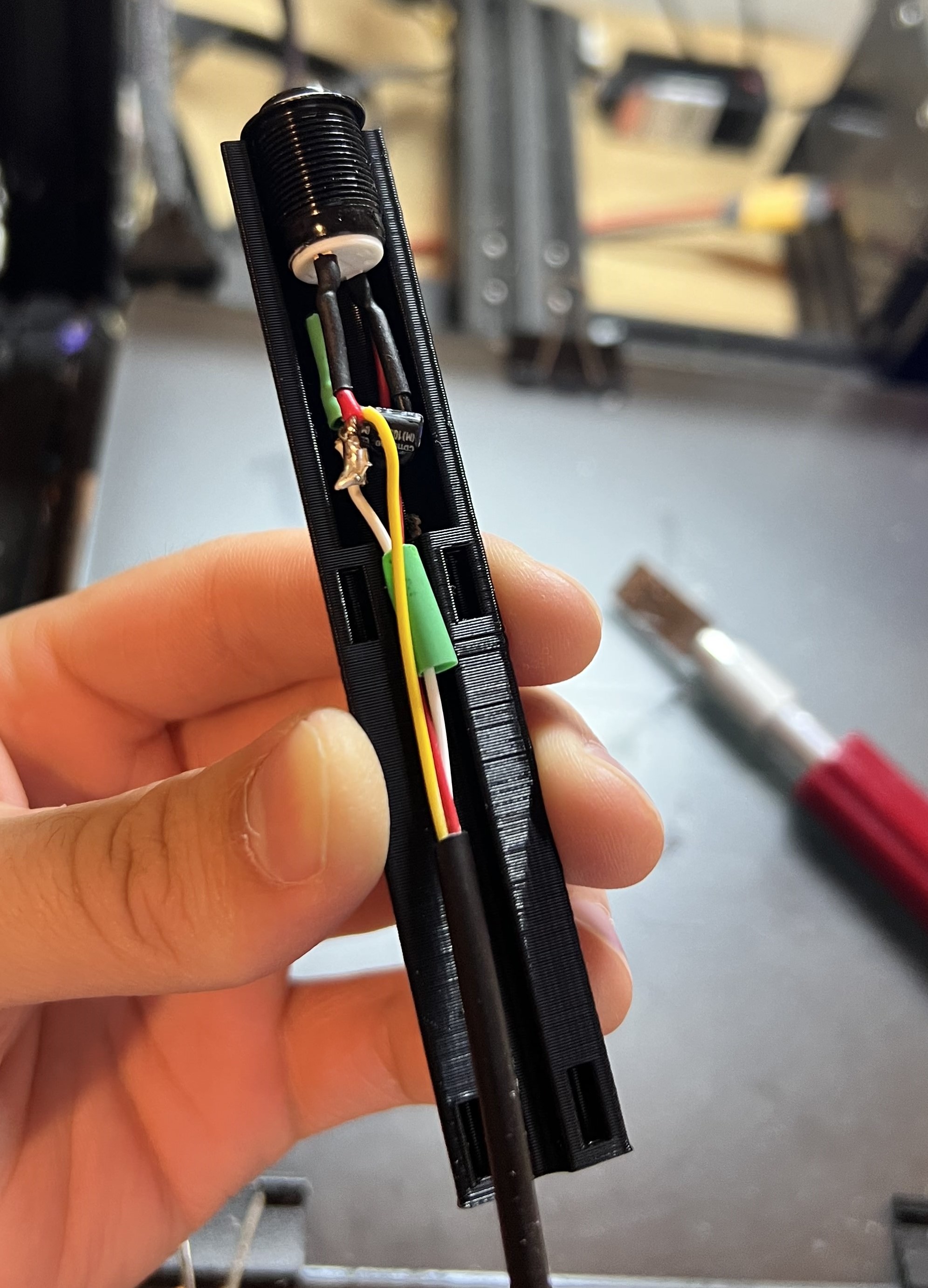
The buzzers were 3D printed to fit these buttons. There’s not much special about them other than that a capacitor is placed inside the buzzer across the ground and signal line to reduce noise and eliminate false presses and missed presses.
Resources
All hardware files for this project can be found at this Google Drive.
Future Improvements
Although I’m very happy with how this project turned out, I see many things that could be improved on in future versions. I already mentioned that the code needs to be rewritten in a cleaner way, that the capacitors and LEDs weren’t very useful on the PCBs, and that building the box by hand was time consuming, but the main change I would make comes down to the screens and how the game is played. Currently, Alex has no way to select the clue or even see which clues are still available. When a player wants to select a clue, he or she has to physically touch the screen. Even if one person is the designated clue selector, all the players must sit close enough to the screen to see it because being able to read the clue quickly gives a big advantage. This leads to up to five people huddled next to each other to view a fairly small screen, and Alex may also be reaching over the table in order to select correct or incorrect.
To fix this, I would suggest that Alex have the sole touch screen where he can see available clues, select the desired clue, see current scores, and receive instructions from the game while the players simply view the clues on a large screen such as a TV. This would eliminate the crowding problem, and allow Alex to have full control of the entire game via the main box which houses the Raspberry Pi. The players would be able to spread out as far as they like from Alex as long as the buzzers can reach. The main problem I see with this is that the GUI shown on the TV would need to be able to adjust to different size screens depending on the size TV used. I’m not sure if PyQt5 has this functionality, but surely there is a way to achieve this. Additionally, this would likely need to be built with a Raspberry Pi 4 since it has two HDMI ports which would allow Alex to have a large enough screen for the thirty or more buttons to choose from.
A lot of this was just me rambling, so if you’d like a more concrete explanation of how something was built, you can find my contact info on my LinkedIn.